Monday 25 February 2019

Sandyford cooking range and back cabin steps

I am busy tackling 'jobs I simply must do before we set off for Nottingham on 20th March'!

One of the trickier issues was the 'steerer's step'. This needs a wooden platform inside the rear doors for the steerer to stand on, outside of the tiller radius. Sounds simple, but quite difficult to achieve. Proper traditional boats would have had a big lump of oak, cantilevered off the steelwork. But because there is a hatch in my rear deck, to access the weedhatch, that approach wouldn't work.

The other issue was the sheer difference in height - 21" between the top of the swims and the rear deck, needing a very steep, short staircase,

So I cobbled this together from some bits of CLS and plywood offcuts, to provide a temporary solution and to see if it worked in practice.


Not pretty, but it serves as a prototype until I can make something better, from nice timber and including storage space.

I've been busy putting the Sandyford cooking range back together too. Hopefully it will be working in cooking mode soon, as soon as it's been properly commissioned.


Monday 18 February 2019

Underfloor heating!

I admit... I'd been putting off tackling the underfloor under the cabin floor. Why? Simply, because to do it, I would have to systematically move everything. And even then, as soon as the UFH panels were down, I would have to protect them from damage.

I finally bit the bullet and cleared the forward half of the cabin. Having located the cooker in its final position, it was a fairly easy matter to lay out the 12mm Celotex and then the UFH panels, to provide the 'pipe map' required.


Once the panels were down, it was a case of wrestling with 120 metres of plastic pipe, trying to persuade it to fit into the grooves!


Finally...!


I then had to cover the newly-laid UFH with every spare piece of plywood I could find, to stack all the materials, tools and other clobber, so I could do the other half of the cabin.


Here is the rear half of the cabin, with Celotex, panels and pipework laid. Note the walking boards.
The next job was to crack on with laying the engineered oak floor boards. This progressed quite smoothly, with all of the various heavy objects coming in handy to weight it down while the glue set.


With the stern half more or less finished, it was time to shift everything yet again!! If I had a pound for every time I've moved all this stuff...


With the floor finished, my next priority was to start putting the cooker back together. The hotplates had got very rusty, but a few minutes with the belt sander soon made a big improvement.


A quick trial assembly confirmed that the lids would stay open, without hitting the cabin side.


And finally... got the tiller drilled to take the pin and fitted the rather lovely hand-made handle.


Tuesday 5 February 2019

Gearbox and engine controls

I had originally thought to use cable controls with a 'Morse' type lever. But the practicality of trying to mate these cables to a vintage engine, coupled with the difficulty of trying to route the cables through the back cabin, made me start considering traditional, speedwheel and lever controls.

Whilst browsing Tony and Paul Redshaw's website (http://www.vintagediesels.co.uk/), I spotted their offer of a complete kit, which seemed just the job. Having collected the kit, I was presented with an interesting collection of trunions, bell cranks, rod ends and various other bits, which all looked pretty confusing. Luckily, they also supplied a very helpful diagram of how it should all go together!

Having figured out some of the basics, i.e. to go forward, the gearbox lever needs to go back, but the D-handle needs to go forward, this dictated how the bell cranks needed to be set up.

But before I could do anything, I had to install the T&G boards to the back cabin and engine room roof.


The gear lever was drilled and tapped to take the ball joint and was linked to the bell crank. The cranks were supported on two pieces of inch-thick ash.


Then the rest of the linkage was completed back to the D-handle, with a detent for neutral.


Fitting the throttle control was reasonably straightworward, after drilling and tapping the throttle bar to take the ball joint. The lever box was located directly above and was connected back via two universal joints.


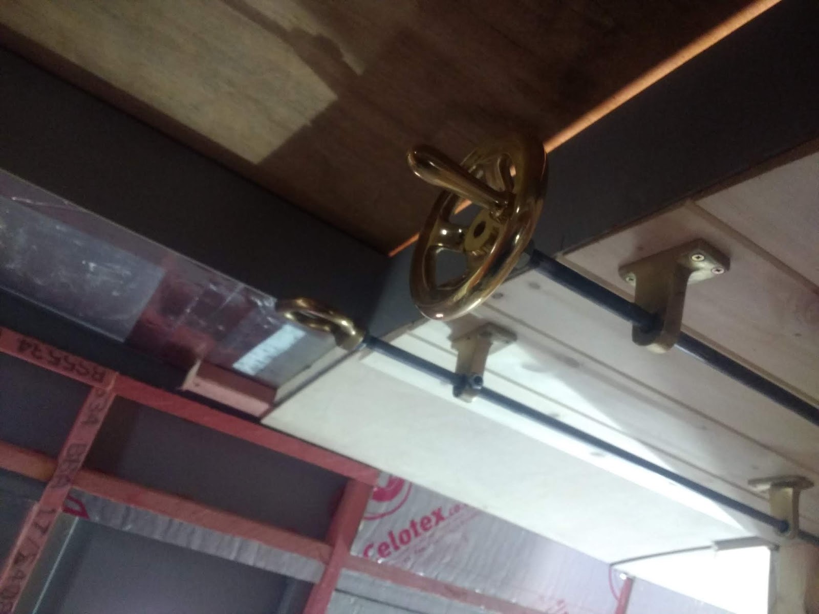
Speedwheel and D-handle in place and working correctly.

Next job was to connect up the fuel lines from the main tanks to the engine. I had had the engine running from a 5-litre can; now it was time to make a proper job!


PVC-coated copper tube, brought through the bulkhead in Copex, to resist abrasion.


Fuel Guard filter in place. This removes water and contaminants from the fuel. I abandoned the idea of including the recirculating function in this location. It involved too many components and joints, with the attendant risk of leaks.


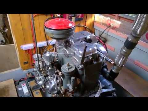
The cooling system is finally complete! It took a while to get some airlocks out of the system, but it's all working nicely now. It took 35L of anti-freeze mix to fill it. Now I was able to run the engine for an extended period and vary the speed accurately with the speedwheel.
The alternator is working well, a little too well in fact. It generates over 100A @28V on tickover, which is somewhat overloading the engine. So I may fit a larger driven pulley to reduce the load a bit.


Maiden voyage and cooker!

It's been an eventful few days! We've been enjoying a spell of unseasonably warm weather, which was predicted to end on the last day...