Sunday 23 December 2018

24V wiring on the narrowboat

Well, it's been quite a busy month, with the majority of my focus on the heavyweight 24V electrics.

At the time of the last post, I'd completed some of the wiring, but was halted as I didn't have a crimper big enough to handle the 70mm2 cables that had to run from the domestic battery bank to the inverter. At full power, the inverter will be pulling 200A from the batteries, so the cables and connections need to be rated appropriately.

Once I had the crimper, it was on to the heavy cabling in earnest. A friend of mine made a couple of bespoke brackets to hold the big 400A isolator switches. These need to be mounted as close as possible to the batteries. Power is then fed through a megafuse to the busbar and is distributed from that point.

It's surprising just how many connections needed to be made to the busbars! I was careful to make the installation as neat as possible, to facilitate tracing and fault-finding if required. Any loose cables were routed in convoluted pipe to prevent chafing.

24V busbars
At the final stages of the shell build, I'd made a mistake when locating the starter battery box. I asked them to place it near the starter motor... as I realised later, it needed to be near the bulkhead with a all the other electrics. So it was out with the angle grinder and a crowbar; before long, I had it loose and was able to relocate it.

Starter battery islolation switch
Next job was to wire up the starter motor. This was an awkward job, as the only safe place to route the cables was along the engine bearer, which was fine, but getting the screws into the cable clamps involved trying use a drill under the engine, whilst holding the cable and the clip - and not really being able to see!


The temperature sensors for the inverter and A2B charger were connected to battery negative and an additional fused supply was taken off to provide unswitched power for the bilge pumps.

The Victron Colour Control unit was connected to the inverter and MPPT controller using the VE Bus and VE Direct cables. It's an impressive piece of kit that tells you what's going on around the system.


That completed the 'power' side of the 24V electrics. The next phase will involve taking cables from the distribution box out to the various lights, pumps and other 24V equipment. The installation just needs labels applying to the key components.

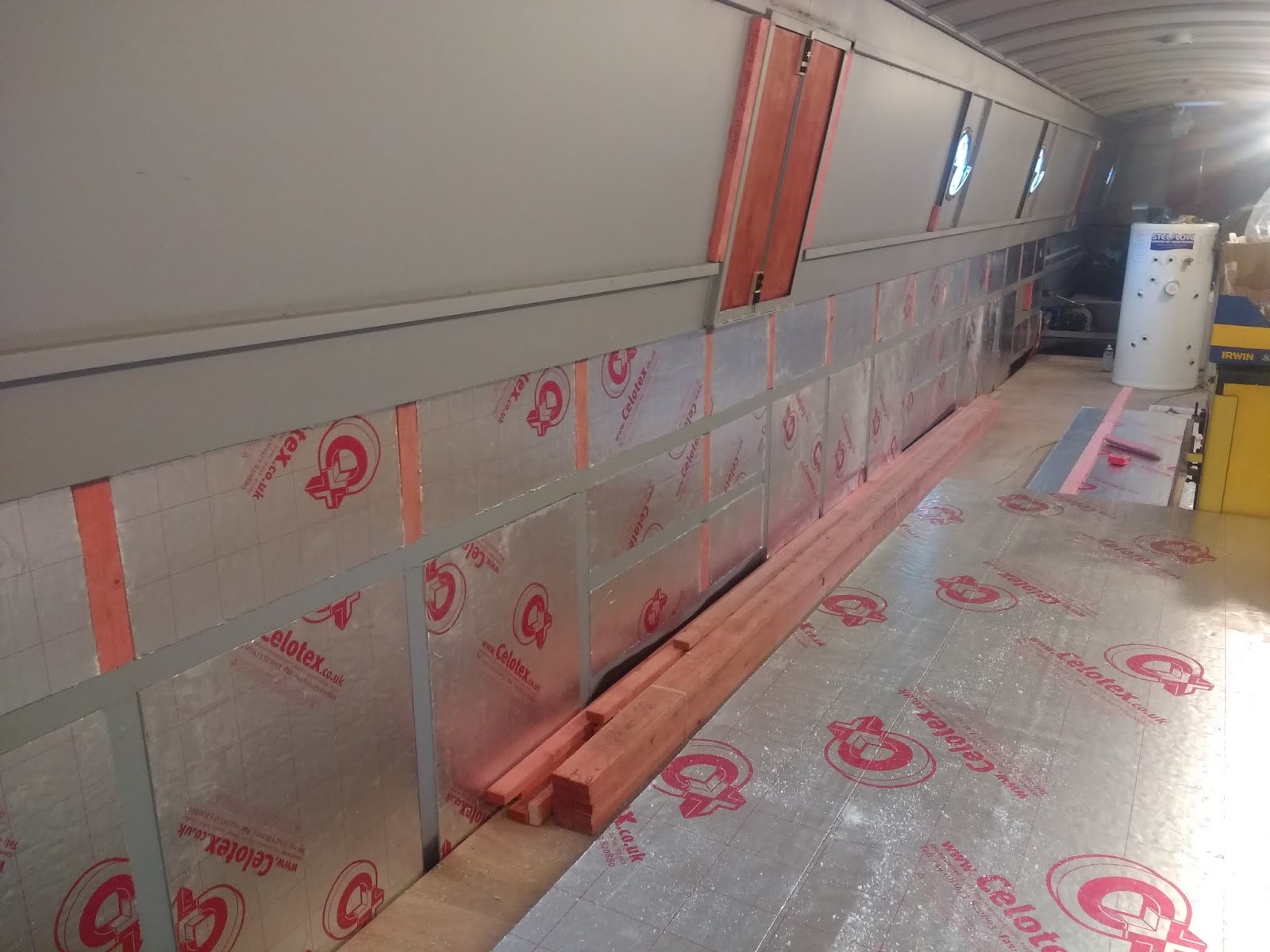
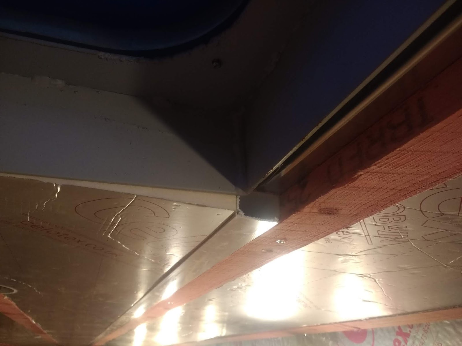
Best practice is to keep 230V AC cables separate from the low voltage DC ones. So the AC is fed through trunking below the gunwale and the DC stuff through trunking in the roof. This is one way the Celotex insulation has worked out very well. The roof has two layers of 12mm, which made a level with the steel roof bearers. I then fixed 25mm battens lengthwise and ran two 25mm x 40mm plastic trunkings right down the boat. The spaces in between were filled with a final layer of 25mm Celotex, giving a total of 49mm under the roof.

Showing trunking in roofspace

By routing a channel, it should be a relatively easy matter to break out of the trunking to supply lights and other equipment.

With the ceiling insulation finshed (hooray!) between the engine room bulkhead and the forward bulkhead, I could now turn my attention to getting that battened and insulated, as it was one of the last remaining areas of bare steel.


Tuesday 11 December 2018

Engine room bulkhead and electrics

As I mentioned in the last post, a key objective was to get a 'decent' source of mains power. The marina only has a 6A supply, which kicks out as soon as you pick up something like a nail gun.

As I have twelve 2V 840Ah batteries on board, the obvious approach was to trickle charge them, overnight and when I'm not there, to have oodles of power when I need it.

So the priority was to construct the engine room bulkhead - a frame of 2" square ash and boarded with 14mm T&G. I had pre-made the ash components in the workshop, so it was a relatively simple matter to assemble the components and fix in place.


Next, on with the T&G boarding...

This is taken from the engine room side, after the first coat of varnish. Next job was to locate and hang the various major electrical components: inverter, consumer unit, solar controller, Victron colour display, Sterling A2B charger, etc.


An electrician friend came down for a few hours and installed an RCD in the Potter's locker (to protect the incoming shoreline), wired up the consumer unit and put in a couple of double sockets, one at each end of the boat. I feel happier now that all the AC is properly protected.
I had an issue with the big battery bank failing to deliver any useful current. It turned out to be one slightly dodgy connection on a battery interlink, now resolved.


With the basic 230V stuff sorted, it was time to turn my attention to the 24V DC cabling. At this point, it's worth explaining that the back of the engine room bulkhead forms the inside of what will be the airing cupboard. This gives a great opportunity to hide a lot of the wiring.


The 155Amp 28V alternator has been removed and wired up...


... and re-installed. This was followed by the busbars, megafuse and 24V distribution panel. This needed a little box making, due to the depth of the fuses and wiring.


With the inverter connected and the battery bank fully charged, it was time for the acid test - a full burn cycle of the Cinderella toilet, purely under inverter power. (This featured in an earlier blog, but in essence, the whole electrical system has been designed to allow repeated use of the toilet, without recourse to the generator or starting the engine.) So I unplugged the shore power and started the toilet operating.


After 50 minutes, the toilet stopped incinerating and went into the cooling phase. Success! The only evidence of its operation was the quiet fan noise and the inverter running its cooling fans during peak load. I'm delighted that the system has passed this aggressive test with flying colours!

It will now be a simple matter to install the toilet: a 13A plug and some plastic 4" pipe out through the roof vent.

I will admit to looking slightly smugly at other boaters, when they are struggling with their poo-laden cassettes, on their way to the Elsan point. I am also very pleased that I won't have to find room for a massive sewage storage tank. I have every confidence now, that this toilet system will be the gold standard of the future.

The Cinderella toilet is available from https://www.leesan.com/shop/all-toilets/incineration-toilets


I now have the hydraulic crimper for the big 70mm cables and connectors, so that's the next job...

Sunday 25 November 2018

Narrowboat fitout - end November update

Well, it's been a rather slow, tedious few weeks.
I really need to get the inverter connected up, so I can run some decent power tools. I also need to get some charge into the two sets of batteries.
But, before I can connect up the inverter, I need a bulkhead to hang it on.
Before I can build the bulkhead, I need to fix the ceiling battens, so I have something to fix to.
Before I can fix the ceiling battens, I need to complete the second layer of insulation...
I also need to inject every gap between the pieces of Celotex with expanding foam, which makes a godawful mess and takes 24 hours to cure fully, so the cutting back process can't be rushed.

I've almost completed the insulation in the engine room and back cabin. This has been complicated by the fact that everything is either curved, angled or both, so every piece has to be custom-fit.

That all pretty well sums up the state of play - a whole bunch of things that are dependent on something else happening. So I've just knuckled down to the (now very tedious) job of fitting all the 12mm Celotex to the ceiling and squirting expanding foam into any gaps.


Next will be the job of applying foil tape to all the joins between the Celotex panels on the ceiling and port side. Although this is another very tedious job, it's vital, as it prevents moisture migrating through to cold steel below.

I don't deny, I will be glad to get this stage finished. Getting the pile of Celotex off the floor and onto the walls/ceilings has helped to make more room.

Hopefully, the next post will be more interesting!

Sunday 11 November 2018

First month - insulating my narrowboat


Time flies, so they say... I've just realised it's been a month since the last post!

Once Calbourne was safely in the water, it was time to take stock a bit. The departure from XR&D had been chaotic, to say the least. All the tools and materials, which had been conveniently stacked outside the boat in the DIY shed, had been more or less thrown into the boat while the crane and lorry were waiting!

So it was a case of sorting things out and trying to store them where they would cause the minimum of obstruction to the next jobs. Easier said than done, but the space in the forecabin was very welcome. The bulkiest material was the 50mm Celotex, so it became a priority to get this insulation onto the walls. 

Not much room to move!
When floated, the boat was already sitting with the stern higher than I would have liked, so I decided to complete the filler pipe and breather for the water tank and do a test fill. I needed to see the effect of a full tank. I had a flow gauge, so I connected it up and turned the tap on. And waited... for nearly two hours. Finally, with 923L showing on the gauge, water came out of the overflow. The bow was now 3" lower and the boat had listed quite a bit to port. Clearly, I needed to shift a lot of ballast toward the stern and to starboard. This was made more difficult, as the cooker was bridging two of the plywood floor panels, but I moved what I could access. 


Fitting the Celotex was fairly straightforward - cut and then fix in place with spray glue. But first, all the battens needed to fixed. Most of these were cut to size in the workshop to save time. After fitting the panels, the gaps behind the steel angles were filled with expanding foam. Once set, it was trimmed back and all joins were covered with foil tape, to provide a continuous vapour barrier. 


Because the cooker was hard up against the port side, it was logical to concentrate on the starboard side. I was keen to see how the 'underfloor' heating pipes would sit in the hull sides, so I pressed on with fitting the horizontal battens. These had to be carefully spaced, to make sure they would accommodate the six pipe runs and the cabling conduit above. A first attempt at fitting the panels revealed an issue - the need to allow room for the pipes to sweep round at the end of each run. This involved some adjustment to the cutting of the polystyrene panels, but I soon had the first two installed. These will be permanently fixed in place with PVA adhesive.

Spot the problem?

A 40mm x 25mm plastic conduit was fitted above the top batten, which left a gap to allow for a section of 30mm Celotex to insulate the bottom of the gunwale.

I then pressed on with getting the port cabin side insulated. With the weather getting colder, I was keen to make my floating steel box a bit cosier! While doing this, I allowed for a channel, to allow the combustion air for the cooker to be drawn up from the bilge.

Next, I started on the ceiling insulation. I found that Celotex is not very bendy, so instead of fitting 25mm as planned, I would have to fit two layers of 12mm, to allow it to follow the curve of the roof. This was quite straightforward, just a bit repetitive!


In between doing the insulation, ProCast finally turned up with the remaining chimney collars and hatch. This was quite a relief, as I'd had to glue pieces of plywood over the holes to keep the weather out.
The hatch is very heavy!
They also brought the porthole liners. It was a relief to see that they fitted neatly into the holes I'd cut in the insulation. They are made of glass fibre, but look remarkably like wood - and should solve the perennial rotting problem.


Although the marina has the benefit of mains hook-up, the supply is limited to 6 Amps. This means that even modest hand-held tools, like a circular saw, kick out the breaker. In order to use more powerful tools, I need to get the inverter connected up.


Outside, Calbourne is going a bright orange colour as she starts to rust. This is causing a few raised eyebrows and more than a few questions! The reason for this is simple. The boat will be grit blasted and painted next Spring. The grit blaster has told me that the millscale will come off the steel better if it's allowed to rust first. Needless to say, I'm looking forward to seeing her looking more respectable!

Friday 12 October 2018

Rollout, transport and launch!

You know that feeling you get on Christmas Eve, when the last shop has shut and you say 'Well, if we haven't got it now...' For me, 4pm on Weds 10th Oct was a bit like that. I would have dearly liked another week, or even a day, to do more work on her, but we were committed.

Forklift trucks were started and as ladders and steps were pulled away for the last time, it had all the feeling of a plane preparing for take-off or a ship about to leave port.


The extending flatbed lorry was positioned up to the wall, the mighty crane was alongside. I was amazed at the size of the thing. The driver told me it could lift 220 tonnes, which seemed a bit OTT, but it was what they had available.


Very slowly, Garry pushed Calbourne on its rollers, out of the shed and into the October sunshine. I have to admit, it was quite an emotional moment, the culmination of a lot of work and planning.


The plan was to take an initial lift to place the bow on the back of the lorry, then reset the strops to get a full, even lift. They went for a lift, but found the boat was tipping down at the bow. The strops were reset forward by a metre or so and then Calbourne gently became airborne!


The lift confirmed my suspicion that there was too much weight too far forward, in spite of the advice that 'two-thirds of the ballast should be forward of the centreline'.


With a bit of effort on the taglines, the boat was soon lowered dead centre on the lorry, the strops were dropped off and securing straps fitted.

A big empty space in the build shed!
Nothing else could be done, except to hope and pray that the cooker didn't break free and cause carnage on the journey. At this point, it's only fair to say a big public 'Thank you' to Garry, Lee, Abdul, Murray and the rest of the XR&D team, for building me my dream boat. Great job, guys!

Before long, the lorry whisked the boat off to their yard to overnight at Newark, ready for an early start to be at March by 8am.


The lorry was already there when we arrived. I was very anxious to get on board to see how everything, especially the cooker, had fared during the trip. But I wasn't allowed anywhere near, so I would have to wait till she was safely on the water.


The gantry was positioned over the boat. There was a tense moment, when I wondered if the gantry would clear the pigeon box, but all was well. Before long, the boat was dangling by the strops again and the lorry was, somewhat disconcertingly, pulled away, leaving the boat dangling in mid-air.


The gantry was steadily steered round to point at the slipway and with a steady push from the tractor, gracefully slid into the water.


My heart was in my mouth slightly, when I saw how deep the stern went in! All kinds of thoughts rushed through my mind... Had I put too much ballast in? How high were those holes above the waterline? Irrational stuff like that. Then suddenly, she was free of the supports and restraints and was bobbing gently on the water, with her counter an inch or so above the water. She floats! Woohoo! Relief.

That part of the drama over, it was now a question of pulling and pushing the boat to the berth, using only my 15m centreline and a borrowed pole. The difficulty was, she had to be pulled backwards out into the river opening, then turned through 90 degrees, then moved into the basin, then turned 90 degrees again, then forward into the berth. The wind was starting to pick up, which threatened to make life difficult.

With only myself to do the job, it was a case of passing the rope over numerous boats to be able to get a pull in the right dirction, then jumping back on to work the pole.


But before too long, I'd got the bow nudged into the berth, when a number of fellow boaters appeared, brandishing poles and offering a hand. With the stern eased round, she slid gracefully into her berth until the bow nudged the wall.


Having secured a couple lines, now I had my opportunity to check inside. With huge relief, I found that both of the ratchet straps had held firm and the cooker was still in situ. Everything else was fine, too. It's been quite a week! But lovely to see Calbourne sitting so pretty on the water at last.


The launch deadline approaches!

I've just looked - my last blog was on 2nd October. With the crane and lorry booked for the 10th, there was still a frightening amount of work left to do. I drove back to the yard in the camper van on 3rd Oct, ready for a long, hard week.

Some of the key things which were still outstanding:

  • Mate the gearbox to the engine
  • Order the propshaft and fit
  • Soundproof generator housing
  • Install the generator
  • Install the alternator on a bespoke bracket
  • Install the thrust bearing and remote greaser
  • Pack the stern gland
  • Install the bilge pump
  • Install locks to the main doors
  • Install the water tank
  • Get the cooker off the ballast blocks to get floor finished
  • Start on battening and insulating
  • Fit the portholes, hatch and door windows.
  • Make and fit guards to cover moving engine parts
  • Secure the cooker ready for transport
  • Burn holes for chimneys, bilge pumps, etc
These were just the main jobs. In between were dozens of smaller jobs which had to be done to get the bigger tasks completed. The major, pain the backside job was to mate the gearbox to the engine (which has no bell housing). I'd already bought an R&D damper plate. This is a round plate with a splined socket to match the shaft on the gearbox. It also has shock absorbers built in. The difficulty was fitting it to the flywheel, so I had to get a custom-made adapter to join the two together.

So far, so good. The big problem was to ensure the spline was accurately aligned - not easy when you have a 65Kg lump dangling from the end of a chain! Then a secondary plate had to be fabricated to support the main gearbox plate. 

After about a day's work, the spline was finally slid into position and the massive support bracket was welded in place.


Now we knew the distance from the prop shaft to the gearbox flange, I could order the main propshaft. When this arrived, it was disappointingly too short and refused to mate with the gearbox. 4 hours later, after a great deal of cursing, filing and hammering, it finally went into place and was bolted up. It was now 9pm on Saturday 6th. Three and a half days left to complete everything else!


Resigned to the fact that sleep was now a luxury, I got into a routine of starting work at 6.30am and finishing at midnight or later.
Next job was to line out the generator pod in the Potter's locker with heavy duty soundproofing material.and bolt in the massive slide rails.


In an effort to reduce the amount of material which would have to get loaded in the boat, I cracked on with battening and fitting some of the 50mm Celotex.


Now the generator could be loaded... the 150Kg lump was hoisted up with the forklift and painstakingly eased into position. All that careful measuring paid off! It fitted within a few millimetres and dropped onto the support rails, ready for bolting and welding.


With about 2 days before the crane was due, the portholes (ordered 4 months previously) started arriving in dribs and drabs. I was very anxious to ensure that the boat would be watertight before leaving the shed. In the end, she was rolled out minus two chimey collars and the Houdini hatch.


Just hours before the lorry was due, we attempted the installation of the water tank. We knew it wouldn't go through the front doors, so it had to be manhandled through the stern doors, then turned horizontal to allow it to go over the engine. 


We were all mighty relieved when it went into place, only needing an inch chopping off the breather pipe to get it to clear.

Murray was thrashing on with burning the required holes in the cabin and hull, fitted the pole & plank rack and refitted the hatch, which I had just lined with ply. 


Just to add to my rising sense of panic, the lorry and crane arrived an hour early! We still had a list of jobs to complete, but the main task now was to secure the cooker on a platform with ratchet straps. This was vital, to prevent it moving in transit. That done, we then started chucking all the tools, equipment and materials on board. There was no time to do the job neatly - it would all have to be sorted later. By this point, I was close to complete exhaustion and was relieved to be able to hand over responsibility to Garry and the team, to get the boat loaded. See next blog, to follow soon!


Tuesday 2 October 2018

Fitting-out of NB Calbourne started!

After the boat had been rolled out of the build shed into the DIY bay, it suddenly became possible to start on some of the basic fitting out. There was a period of about 3 weeks where the space in the shed was available before the next booking, so it was a case of cracking on, putting in very long days to get the most done in the time available. With launch day set for 11th October, the pressure was on!

I'd found that the most cost-effective way to ballast the boat, was to use high density concrete blocks. These weigh in at around 20Kg each, so two pallets of 72 made 2.8 tonnes.


The blocks dropped in neatly between the bearers. I had calculated that nine extra blocks were needed on the port side to counter the weight of the battery bank and other items. Next job was to fix the crossways battens to the bearers to clear the top of the blocks, then further lengthwise ones. This gives a good support for the floor and gives a 30mm air gap for bilge ventilation. Note the additional battens in the area where the cooker will go!


Next, in with the plywood sub-floor. The cooker is now on rollers, pending movement to its final position. It's very heavy!


At the stern, the prop shaft and prop have been installed:


Stop cocks and fuel lines have been fitted to the massive fuel tank in the bow. The fuel lines, which are PVC-coated 10mm copper tube, have been run down the length of the boat in very hard PVC tube to resist abrasion. 

The service batteries - twelve 840Ah 2V cells, wired in series, have been installed in a custom-made steel battery box. The batteries are fitted with auto-venting and auto-watering systems. The starter batteries are on the opposite side.


Plywood inserts have now been fitted to all the doors, including the Potter's locker, where the generator will be housed.


I'll cover the installation of the gearbox and alternator in the next blog!

Maiden voyage and cooker!

It's been an eventful few days! We've been enjoying a spell of unseasonably warm weather, which was predicted to end on the last day...