Monday 4 March 2019

Maiden voyage and cooker!

It's been an eventful few days! We've been enjoying a spell of unseasonably warm weather, which was predicted to end on the last day of February. With all of the mechanical stuff sorted and the steerer's step built, it seemed the ideal opportunity to go for a trial cruise.


Heading out of the river onto the Middle Level, I was able to test the boat at a range of speeds. I was pleased that she handles well and steers a straight course when you let go of the tiller. I was also pleased that even at higher speeds (for a narrowboat), she produces little bow wave and no stern wake at all.

For a maiden voyage, it was really quite uneventful - everything worked as it should. I took the boat to Floods Ferry, about an hour away, turned and came back.

The next job I got on with was the framework for the engine room walkway. For months, I've been stumbling over wobbly concrete blocks, so it will be great to get this bit of floor finished.


The floor is made in sections, to allow access to the bilge and starter batteries.


Today, the plumbers arrived to commission the cooker. After me answering lots of questions about the installation, they were able to get on with installing a fire valve and the fuel connections. With the electricity connected, they were soon able to do a test run on the cooker burner. 


Success! The burner fired up and the cooker started to heat. After a bit of tweaking, it was declared operational. The cooker is remarkable - it runs on diesel and after about 10 minutes, you could boil a kettle. After 20 minutes, you could be roasting in the oven. It also gives off a lovely cosy warmth.


Getting the cooker working is a massive step towards having a usable boat!


Monday 25 February 2019

Sandyford cooking range and back cabin steps

I am busy tackling 'jobs I simply must do before we set off for Nottingham on 20th March'!

One of the trickier issues was the 'steerer's step'. This needs a wooden platform inside the rear doors for the steerer to stand on, outside of the tiller radius. Sounds simple, but quite difficult to achieve. Proper traditional boats would have had a big lump of oak, cantilevered off the steelwork. But because there is a hatch in my rear deck, to access the weedhatch, that approach wouldn't work.

The other issue was the sheer difference in height - 21" between the top of the swims and the rear deck, needing a very steep, short staircase,

So I cobbled this together from some bits of CLS and plywood offcuts, to provide a temporary solution and to see if it worked in practice.


Not pretty, but it serves as a prototype until I can make something better, from nice timber and including storage space.

I've been busy putting the Sandyford cooking range back together too. Hopefully it will be working in cooking mode soon, as soon as it's been properly commissioned.


Monday 18 February 2019

Underfloor heating!

I admit... I'd been putting off tackling the underfloor under the cabin floor. Why? Simply, because to do it, I would have to systematically move everything. And even then, as soon as the UFH panels were down, I would have to protect them from damage.

I finally bit the bullet and cleared the forward half of the cabin. Having located the cooker in its final position, it was a fairly easy matter to lay out the 12mm Celotex and then the UFH panels, to provide the 'pipe map' required.


Once the panels were down, it was a case of wrestling with 120 metres of plastic pipe, trying to persuade it to fit into the grooves!


Finally...!


I then had to cover the newly-laid UFH with every spare piece of plywood I could find, to stack all the materials, tools and other clobber, so I could do the other half of the cabin.


Here is the rear half of the cabin, with Celotex, panels and pipework laid. Note the walking boards.
The next job was to crack on with laying the engineered oak floor boards. This progressed quite smoothly, with all of the various heavy objects coming in handy to weight it down while the glue set.


With the stern half more or less finished, it was time to shift everything yet again!! If I had a pound for every time I've moved all this stuff...


With the floor finished, my next priority was to start putting the cooker back together. The hotplates had got very rusty, but a few minutes with the belt sander soon made a big improvement.


A quick trial assembly confirmed that the lids would stay open, without hitting the cabin side.


And finally... got the tiller drilled to take the pin and fitted the rather lovely hand-made handle.


Tuesday 5 February 2019

Gearbox and engine controls

I had originally thought to use cable controls with a 'Morse' type lever. But the practicality of trying to mate these cables to a vintage engine, coupled with the difficulty of trying to route the cables through the back cabin, made me start considering traditional, speedwheel and lever controls.

Whilst browsing Tony and Paul Redshaw's website (http://www.vintagediesels.co.uk/), I spotted their offer of a complete kit, which seemed just the job. Having collected the kit, I was presented with an interesting collection of trunions, bell cranks, rod ends and various other bits, which all looked pretty confusing. Luckily, they also supplied a very helpful diagram of how it should all go together!

Having figured out some of the basics, i.e. to go forward, the gearbox lever needs to go back, but the D-handle needs to go forward, this dictated how the bell cranks needed to be set up.

But before I could do anything, I had to install the T&G boards to the back cabin and engine room roof.


The gear lever was drilled and tapped to take the ball joint and was linked to the bell crank. The cranks were supported on two pieces of inch-thick ash.


Then the rest of the linkage was completed back to the D-handle, with a detent for neutral.


Fitting the throttle control was reasonably straightworward, after drilling and tapping the throttle bar to take the ball joint. The lever box was located directly above and was connected back via two universal joints.


Speedwheel and D-handle in place and working correctly.

Next job was to connect up the fuel lines from the main tanks to the engine. I had had the engine running from a 5-litre can; now it was time to make a proper job!


PVC-coated copper tube, brought through the bulkhead in Copex, to resist abrasion.


Fuel Guard filter in place. This removes water and contaminants from the fuel. I abandoned the idea of including the recirculating function in this location. It involved too many components and joints, with the attendant risk of leaks.


The cooling system is finally complete! It took a while to get some airlocks out of the system, but it's all working nicely now. It took 35L of anti-freeze mix to fill it. Now I was able to run the engine for an extended period and vary the speed accurately with the speedwheel.
The alternator is working well, a little too well in fact. It generates over 100A @28V on tickover, which is somewhat overloading the engine. So I may fit a larger driven pulley to reduce the load a bit.


Tuesday 29 January 2019

Filters, fuel and Diesel Bug!

Having got the engine running (albeit from a 5L (1-gallon for Brexiteers) can), it was time to bite the bullet and drag out the box of components from Fuel Guard to assemble the fuel filter assembly.

My original plan was to have a recirculating fuel filter in the Potter's locker. After a bit of head scratching (seems to be a frequent event these days), I figured I could use the system as both a normal inline filter and a recirculating, polishing system.

The real question was where to locate it. The obvious place was the devoid-of-obstructions, newly-installed rear bulkhead, until I noticed that the filter was set up to flow the wrong way. More head scratching.

So the filter ended up on the electrically-crowded forward bulkhead. Due to space constraints, the pump and valve assembly had to be mounted separately.


A non-return valve was fitted to the engine feed line, to stop the fuel draining back. After connecting the feed and return lines from the main fuel tanks, it was time to focus on the engine room and back cabin roof lining. My ambition was to install the speedwheel and gear controls, but to be able to do that, I needed something to fix all the parts to. So it was on to cutting lengths of T&G boarding to line the roof.


Hopefully, a few more days should see the controls in place and the boat technically movable!


Wednesday 23 January 2019

First run of the Gardner 3LW

I don't really know why it's taken so long to get the engine running, to be honest. The beautiful Gardner 3LW has been installed in the shell for months, but it's never really been a top priority to get it running. There have also been some good reasons why I couldn't, such the starter motor not being wired up, then finding that the starter motor didn't work properly, not having the exhaust components to hand, no gearbox oil cooler, no cooling system, and so on.
But mainly, it's just all those other jobs, like insulating the boat, which were really more urgent.

Anyway, the other day, the replacement starter motor arrived, courtesy of Iain Parker at ICS Online.
(Quick plug for this company here... they are very knowledgeable and incredibly helpful. Top service!) It only took a few minutes to install and was turning the engine over very nicely.


This gave me the motivation to get the gearbox oil cooler installed. This was a tricky one, because the gearbox was at one end of the engine room and the coolant pipes were at the other. I figured that the only place where it could sensibly be fitted, was on the engine bearer. Then there was the small matter of sourcing 10mm bore hose which could withstand 20 Bar!

The location of the cooler meant I needed a few more bends for the engine cooling system, but with those on order, I could now fill the gearbox with oil. The exhaust components were just screwed together by hand for now...


With the addition of some plastic tube and a can of fuel, it was time to try and bleed the fuel system. I struggled to find any useful information on the internet, so it was down to a bit of trial and error, made more complicated by the fact that the engine had to be turned by hand to allow the manual lift pump to work. During the months that the engine had stood idle, many of the fuel-related components had got very stiff, so I was worried this was going to be an issue.


However, after a number of unsuccessful engine spins, there was the unmistakable sound of it firing on one cylinder. A bit more bleeding of the fuel, another go with the starter, then all of a sudden, the engine sprang to life!


As the engine has no coolant at this stage, I was limited to the amount of running time, but was able to test the prop in gear, both forward and backwards. All seemed well, with a good strain being exerted on the mooring lines!

Now I was keen to check that the big 155 Amp, 24 Volt alternator was working. I found a 24V bulb and wired it up to battery positive and the Lamp terminal on the alternator. Another brief run of the engine saw the Sterling A2B charger spring into life, with a row of green LEDs showing. Next job is to fit a Hall effect ammeter to the cable, to show the charge current. First indications are that the pulley ratios are about right. Phew. The system will need more testing, by discharging the batteries, so they 'demand' full charge current.

Next jobs are to complete and fill the coolant system and make the permanent fuel connections; secure the silencer to the roof collar, etc. But these are minor things. It might not be too long before I'll be reversing Calbourne out of her mooring, onto the river for a little test cruise!
Happy days... good progress!


Saturday 19 January 2019

Cracking on with the essentials

It's been a funny old couple of weeks, but some good progress to report.

When I returned to the boat in the New Year, it dawned on mt that I had just over two months to get the boat into a sailable condition! The grit blaster and paint tunnel were booked for the beginning of April, so I had to be able to set off for Nottingham around 15th March.

This had the effect of focusing me onto 'Jobs That Really Must Be Done To Be Able To Move The Boat', instead of the jobs that I was most interested in!

I started writing a list and was surprised at how basic some of the essential jobs were, e.g.


  • Fit tiller
  • Get engine running: cooling system, starter motor, gearbox cooling, fuel supply, etc
  • Flooring over propshaft
  • Something to stand on whilst steering
  • Steps to stern
  • Water pump
  • Install toilet (thankfully simple)
  • Buy and fit fenders
  • Ideally, get the cooker installed and working: two 11-day trips on 'ping' meals???


I picked the water pump as the first task, as I wanted it out of the way and thought it would be a quick win. It should have been simple: screw pump assembly to a piece of plywood and connect up. Until I realised that all the holes were covered by the pump itself, so I ended up having to fix captive bolts into the wood, fit the pump over, then fiddle and faff to get washers and nuts on. Four hours later...

Twin pump assembly, ready for in/out connections

Who designs this stuff? Don't they give any thought to the poor *** who's got to install it??
Having run the DC supply down the boat, I was able to test the pumps by pumping the tank contents overboard. The twin pump setup worked impressively, delivering through a 22mm pipe at full bore. They emptied the 900 litre tank in under 30 minutes.

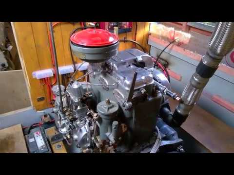
The next key job was 'Get The Engine Running'! As with so many things on this build, one task is dependant on two or three others. The engine needs a cooling system; the cooling system needs a header tank; the header tank needs to go on s bulkhead; before the bulkhead goes in, the ceiling insulation needs finishing... and so it goes.

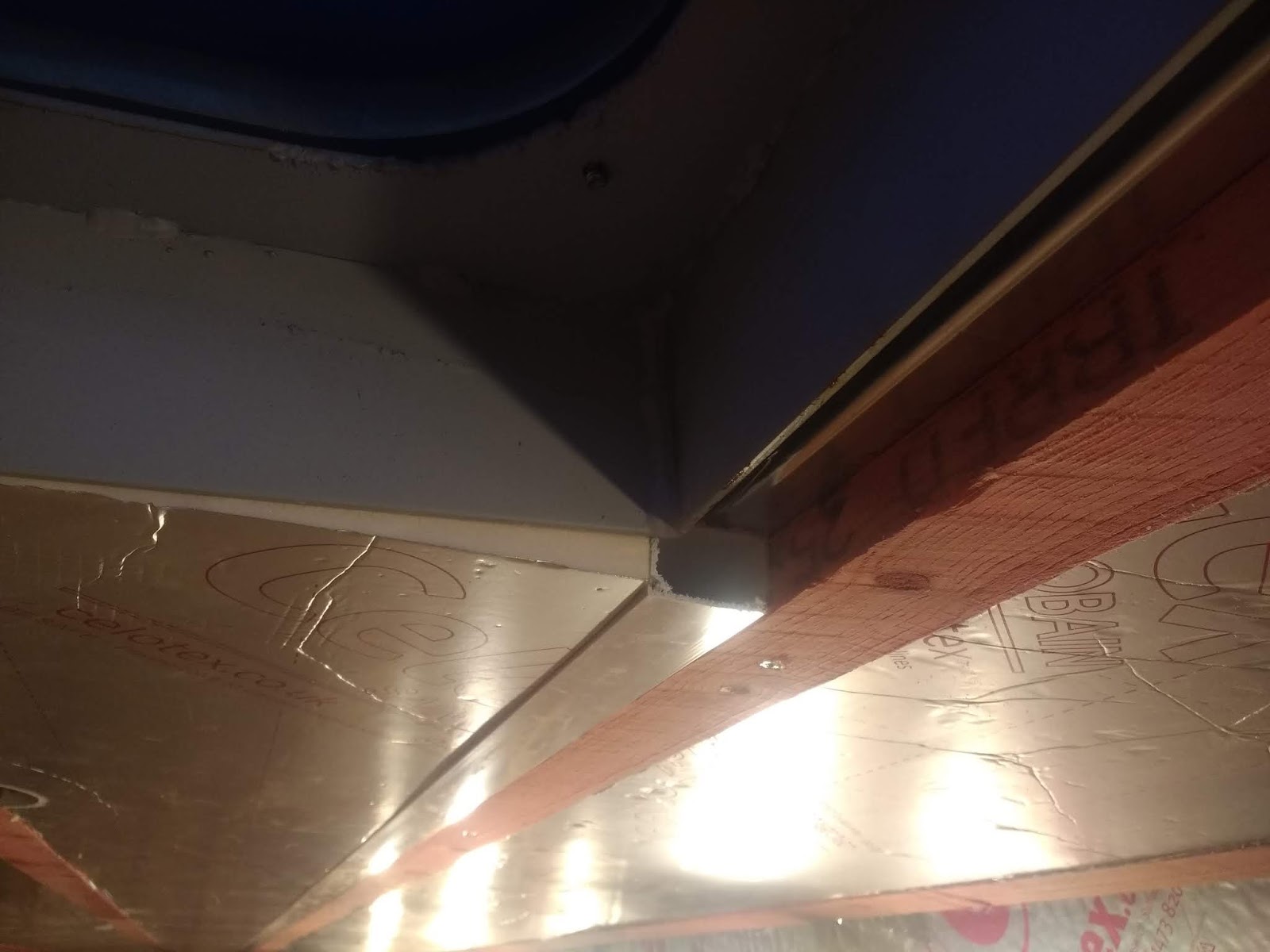
So it was out with the Celotex and spray glue, then off to the builders merchant to get T&G boarding, ready for the bulkhead. Happily, I'd pre-made the ash framework in the workshop weeks previously, so it was a fairly straightforward job to fit it.


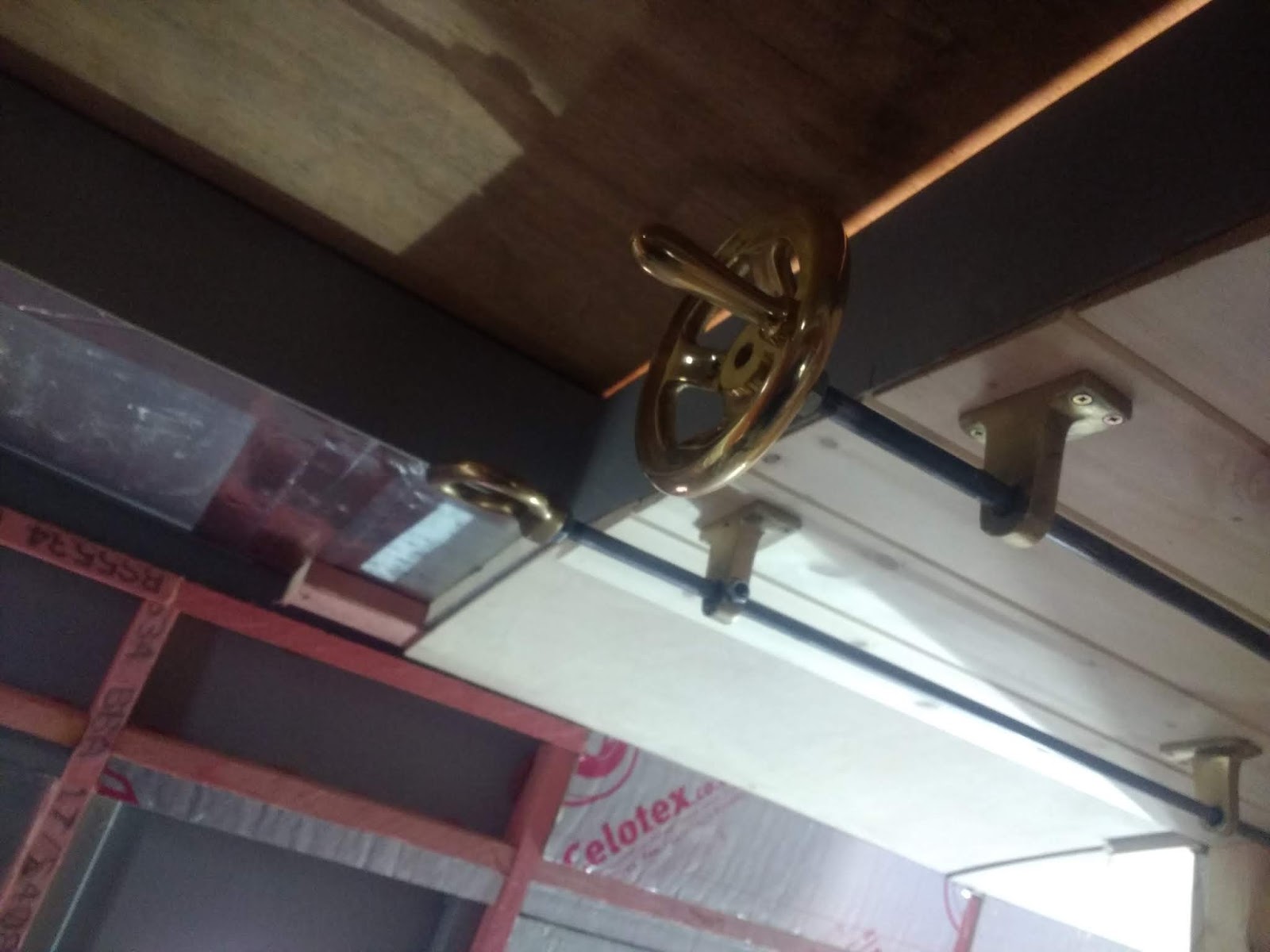
Fitting the T&G boarding was a nice easy job, then I was able to fit the lovely brass header tank (supplied by Tony Redshaw Vintage Diesels) and connect up the feed hose.


The PRM 500 gearbox needs an oil cooler. This is not normally an issue on modern engines, because they arrange somewhere convenient to fit it. The problem with fitting a vintage engine is that... nothing fits!! The cold side of the cooling system is at one end, the gearbox is at the other, so the compromise was to fix the cooler to the engine bearer. This was another case in point - all the blasted screw holes covered by the unit itself!! I think these designers think we have flexible, right-angled screwdrivers!

Added to that, the PRM 500 manual states that the system needs to be rated at 20Bar. That's 300psi in old money. A lot of searching on eBay produced some rubber hose, sheathed in stainless steel. Hopefully it will be OK!


Next, the starter motor. I  had tried spinning the engine, but the starter failed to engage. The pinion just kept hitting the flywheel, making a terrible din and was starting to damage the flywheel rack.


A phone call to the most knowledgeable Iain Parker of ICS Online solved the problem. He supplied a rebuilt replacement starter motor, which took a few minutes to fit. The new motor worked perfectly and turned the engine over without a problem. Progress!

Having fitted the oil cooler, the next challenge was to route all the cooling water pipes around everything else. This involved ordering a bunch of various bends, but at least it will fit and work.


More on the engine next time!


Wednesday 2 January 2019

Installing underfloor heating in my narrow boat

Just to recap a bit on previous posts...

One of the main reasons given for not installing 'wet' underfloor heating in a boat, is the lack of exposed floor area. This is a fair point - an awful lot of it is covered by various cupboards and other furniture.
But one day, I had a lightbulb moment, which was to run the UFH pipes along the hull sides, as well as the floor. Doing this would make a massive difference to the exposed area.

The only issue was dimensioning the thermal panels to fit. I needed to allow for three 50mm battens, to support the lining, and I wanted to run a 40mm conduit along the top for 230V cables. All of which left it very tight for fitting in the bends at the end of each pipe run!

But with some careful measurement, it all proved just possible. After a few false starts, I set to, cutting the panels to fit in between the battens.


The polystyrene panels make an awful mess when you cut them - the bits seem to get everywhere, but thank goodness for the cordless Dyson!

The panels were fixed in place with a few dabs of SikaFlex. So far, so good. I have a feeling that fitting and securing the pipes is going to be a little trickier!

This photo shows the port side, where the oil fired cooker will go. I have provided vents to allow fresh air to be drawn from the bilge. These line up with the combustion air intakes on the back of the cooker. The idea is to provide the required air without a draught, whilst ventilating the bilge.


Meanwhile, the celing still needed finishing. I had bought a couple of mini Acrow props - these proved to be absolutely invaluable as a third (and fourth!) hand, for holding the battens while they were secured with self-drilling screws.


Once the lengthwise battens were in place, I was able to add the remaining layer of 25mm Celotex and apply yet more foil tape to complete the ceiling insulation.

The BSS guys aren't keen on 230V cables being located with DC ones in the same conduit, so I've run two lengths of 40mm conduit right down the length of the boat to contain them in the roof space.
These should make it quite easy to connect up ceiling lights, as well as running the long cable runs to things like the tunnel light.


Well, that was it for 2018. I suppose, considering the boat wasn't launched till mid-October, I've not made bad progress. But I'm very mindful of the fact that in just over 2 months, I need to have the boat in a cruise-able and semi-habitable state. Around the middle of March, I need to set off on a 12-day trip to Nottingham, where 'Calbourne' will be grit-blasted and painted.

Hmmm... need to start thinking about the engine cooling system, exhaust, controls... plus a few other minor details!

Sunday 23 December 2018

24V wiring on the narrowboat

Well, it's been quite a busy month, with the majority of my focus on the heavyweight 24V electrics.

At the time of the last post, I'd completed some of the wiring, but was halted as I didn't have a crimper big enough to handle the 70mm2 cables that had to run from the domestic battery bank to the inverter. At full power, the inverter will be pulling 200A from the batteries, so the cables and connections need to be rated appropriately.

Once I had the crimper, it was on to the heavy cabling in earnest. A friend of mine made a couple of bespoke brackets to hold the big 400A isolator switches. These need to be mounted as close as possible to the batteries. Power is then fed through a megafuse to the busbar and is distributed from that point.

It's surprising just how many connections needed to be made to the busbars! I was careful to make the installation as neat as possible, to facilitate tracing and fault-finding if required. Any loose cables were routed in convoluted pipe to prevent chafing.

24V busbars
At the final stages of the shell build, I'd made a mistake when locating the starter battery box. I asked them to place it near the starter motor... as I realised later, it needed to be near the bulkhead with a all the other electrics. So it was out with the angle grinder and a crowbar; before long, I had it loose and was able to relocate it.

Starter battery islolation switch
Next job was to wire up the starter motor. This was an awkward job, as the only safe place to route the cables was along the engine bearer, which was fine, but getting the screws into the cable clamps involved trying use a drill under the engine, whilst holding the cable and the clip - and not really being able to see!


The temperature sensors for the inverter and A2B charger were connected to battery negative and an additional fused supply was taken off to provide unswitched power for the bilge pumps.

The Victron Colour Control unit was connected to the inverter and MPPT controller using the VE Bus and VE Direct cables. It's an impressive piece of kit that tells you what's going on around the system.


That completed the 'power' side of the 24V electrics. The next phase will involve taking cables from the distribution box out to the various lights, pumps and other 24V equipment. The installation just needs labels applying to the key components.

Best practice is to keep 230V AC cables separate from the low voltage DC ones. So the AC is fed through trunking below the gunwale and the DC stuff through trunking in the roof. This is one way the Celotex insulation has worked out very well. The roof has two layers of 12mm, which made a level with the steel roof bearers. I then fixed 25mm battens lengthwise and ran two 25mm x 40mm plastic trunkings right down the boat. The spaces in between were filled with a final layer of 25mm Celotex, giving a total of 49mm under the roof.

Showing trunking in roofspace

By routing a channel, it should be a relatively easy matter to break out of the trunking to supply lights and other equipment.

With the ceiling insulation finshed (hooray!) between the engine room bulkhead and the forward bulkhead, I could now turn my attention to getting that battened and insulated, as it was one of the last remaining areas of bare steel.


Maiden voyage and cooker!

It's been an eventful few days! We've been enjoying a spell of unseasonably warm weather, which was predicted to end on the last day...